Blind via aspect ratio
"Blind via aspect ratio" is commonly interpreted as "the aspect ratio of blind vias" or "the width-to-height ratio of blind vias".In printed circuit board (PCB) design, a blind via is a plated through-hole that connects internal layers but is not visible or accessible from the outer layers. The aspect ratio refers to the ratio of the length to the diameter of the blind via.
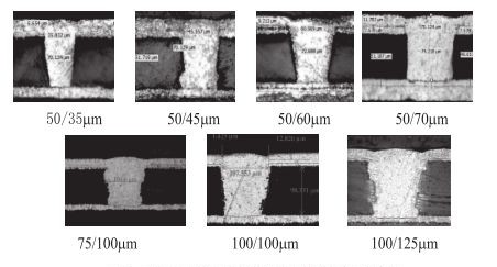
The aspect ratio of blind vias is an important parameter. Different manufacturers may have different manufacturing capabilities. Generally, most manufacturers can produce blind vias with an aspect ratio of 6:1 to 10:1. IPC reliability standards usually stipulate that the aspect ratio of blind vias ranges from 6:1 to 8:1.
For example, the aspect ratio of mechanical blind vias may be 1:1, with a maximum diameter of 0.4mm, a minimum diameter of 150μm, a blind via pad diameter of 450μm, and a ring size of 127μm; the aspect ratio of laser blind vias may also be 1:1, with a maximum diameter of 0.1mm, a minimum diameter of 100μm, a blind via pad diameter of 254μm, and a ring size of 150μm.
In practical applications, factors such as the aspect ratio of blind vias need to be considered because it will affect the performance, manufacturing process, and cost of the PCB. A larger aspect ratio may require stricter drilling tolerances to ensure the accuracy of drilling; while a smaller aspect ratio may limit the electrical performance or wiring density of the blind via. When designing a PCB, an appropriate aspect ratio of blind vias needs to be selected based on specific needs and the capabilities of the manufacturer.
The concept of aspect ratio is not only applicable to blind vias but is also widely used in other fields, such as screen ratios (the ratio of the width to the height of the screen). Common screen ratios include 4:3, 16:9, etc. Different screen ratios are suitable for different scenarios and requirements. For example, the 16:9 widescreen ratio is closer to the golden ratio and is suitable for watching movies, and is increasingly applied in more display devices.
If the "Blind via aspect ratio" you want to know does not refer to the aspect ratio of blind vias in PCB design, you can provide more background information or context so that I can answer your question more accurately.

Introduce the specific calculation method of the aspect ratio of blind vias
The calculation method of the aspect ratio of blind vias is: Aspect Ratio (Conformal Mask) = (T + C) / D, where T represents the thickness of the dielectric, C represents the copper thickness before drilling, and D represents the aperture of the blind via.
It should be noted that the units of each parameter must be consistent during the calculation. For example, if the units of T and C are millimeters, then the unit of D also needs to be millimeters; if the units of T and C are mils, then the unit of D also needs to be mils.
For example, if the dielectric thickness T of a certain blind via is 0.2 millimeters, the copper thickness C before drilling is 0.01 millimeters, and the aperture D is 0.1 millimeters, then the aspect ratio of this blind via is: (0.2 + 0.01) ÷ 0.1 = 2.1.
In addition, there is another calculation method for the aspect ratio (Large Window), which is: (T + 2C) ÷ D. However, this method is less commonly used. In practical applications, the specific method used may vary depending on different processes or standards. At the same time, the size of the aspect ratio of blind vias will have an impact on the manufacturing of PCBs, such as the difficulty of electroplating and filling the holes, wiring density, heat dissipation performance, etc. An appropriate aspect ratio needs to be selected based on specific product requirements and manufacturing process capabilities.
What are the impacts when the aspect ratio of blind vias is too large or too small?
When the aspect ratio of blind vias is too large or too small, it will bring some influences to the manufacturing of PCBs. The specific details are as follows:
Impacts of a too large aspect ratio of blind vias:
- Increased difficulty in electroplating and filling the holes: As the aspect ratio of blind vias increases, achieving "super filling" of the blind vias becomes increasingly difficult. This is because the current distribution within the hole presents a drum-shaped pattern, resulting in a large amount of copper deposited on the surface and the edge of the hole. It is difficult to ensure that the area in the center of the hole where copper is needed reaches the standard thickness. In severe cases, it may cause the absence of the copper layer, leading to the scrapping of multi-layer PCBs.
- Increased cost: It may require the use of more advanced drilling techniques and special electroplating additives, which will increase production costs.
- Reduced reliability: A larger aspect ratio may lead to an increased non-uniformity of the structure within the hole, thereby affecting the reliability and electrical performance of the PCB.
Impacts of a too small aspect ratio of blind vias:
- Limited wiring density of aspect ratio of blind vias: It is impossible to make full use of the space of the PCB, limiting the layout and density of the circuits. This may not be conducive to achieving the miniaturization and high-performance requirements of electronic products.
- The heat dissipation performance may be affected to a certain extent: Relatively small blind vias aspect ratio may have relatively weaker heat dissipation capabilities.
In actual PCB design and manufacturing, an appropriate aspect ratio of blind vias needs to be selected based on specific product requirements and manufacturing process capabilities. Generally, methods such as optimizing drilling parameters, electroplating processes, and using appropriate planarization agents are used to control the filling effect and quality of blind vias to achieve better performance and reliability. At the same time, with technological advancements, such as the development of advanced laser drilling and electroplating technologies, it also helps to address the challenges brought by the aspect ratio of blind vias and achieve higher-quality and more complex PCB manufacturing.
What are the characteristics and precautions for the aspect ratios of laser blind vias and mechanical blind vias?
Blind vias are located on the top and bottom surfaces of printed circuit boards and have a certain depth. They are used for the connection between surface circuits and internal circuits. The depth and diameter of the holes usually do not exceed a certain ratio. In PCB design, the aspect ratio of blind vias is an important parameter that affects signal integrity, manufacturing feasibility, and other aspects. For example, a higher aspect ratio may require more strict drilling tolerances to ensure the accuracy of drilling. In high-speed designs, an appropriate aspect ratio of blind vias helps control impedance, reduce noise, and thereby ensure signal quality. The following are the characteristics and precautions for the aspect ratios of laser blind vias and mechanical blind vias:
- Characteristics:
- The aspect ratio of laser blind vias: The diameter of laser blind vias is relatively small, generally around 0.1mm. Therefore, their aspect ratios can be relatively large, usually reaching more than 10:1. However, the depth of laser blind vias is limited, generally only reaching about 0.5mm.
- The aspect ratio of mechanical blind vias: The diameter of mechanical blind vias is relatively large, generally above 0.2mm. Therefore, their aspect ratios are relatively small, usually between 6:1 and 8:1. However, the depth of mechanical blind vias can be relatively deep, generally reaching above 1.0mm.
- Precautions:
- The aspect ratio of laser blind vias: Due to the small diameter of laser blind vias, it is necessary to pay attention to controlling the energy and focus point of the laser during the drilling process to avoid over-sized or under-sized drilling. In addition, since the depth of laser blind vias is limited, it is necessary to pay attention to controlling the depth of blind vias during the design to avoid affecting the transmission quality of signals.
- The aspect ratio of mechanical blind vias: Due to the large diameter of mechanical blind vias, it is necessary to pay attention to controlling the drilling speed and pressure during the drilling process to avoid over-sized or under-sized drilling. In addition, since the depth of mechanical blind vias can be relatively deep, it is necessary to pay attention to controlling the depth and aspect ratio of blind vias during the design to avoid affecting the transmission quality of signals and the reliability of the circuit board.
It should be noted that different manufacturers may have different manufacturing capabilities, and the aspect ratios of blind vias they can handle may also vary. Generally speaking, most manufacturers should be able to handle blind vias with aspect ratios between 6:1 and 10:1. PCB reliability standards usually stipulate that the aspect ratio of blind vias is between 6:1 and 8:1. An aspect ratio of 8:1 is considered a capability that PCB manufacturers need to have. During PCB design and manufacturing, it is necessary to consider the aspect ratio of blind vias to balance performance requirements and actual manufacturing capabilities. At the same time, other factors such as layer planning, the setting of capture pads, the stack-up structure of the circuit board, manufacturing complexity, and test limitations also need to be comprehensively considered.
What are the differences in application scenarios between laser blind vias aspect ratio and mechanical blind vias aspect ratio?
The application scenarios of laser blind vias aspect ratio and mechanical blind vias aspect ratio differ in the following ways:
Laser blind vias aspect ratio:
1. High-density PCBs: Commonly used in designs with high circuit density and limited space, such as the mainboards of high-end smartphones and tablets.
2. High-frequency and high-speed signal transmission: Well-suited for applications with extremely demanding signal integrity requirements, like communication equipment and servers.
3. Complex multilayer PCBs: Facilitates efficient interconnections between different layers in multilayer PCBs with complex wiring.
Mechanical blind vias aspect ratio:
1. Relatively low-density PCBs: Applied in products where circuit density requirements are not as strict, such as some industrial control devices and automotive electronics.
2. High-current applications: Due to the larger via diameter, they can handle larger currents and are suitable for scenarios like power distribution.
3. Cost-sensitive products: Preferred in cases where cost control is crucial and performance requirements are not exceptionally high.
How to determine the aspect ratio of blind vias based on factors such as PCB thickness, line width, and line spacing?
Determining the aspect ratio of blind vias requires comprehensive consideration of factors such as PCB thickness, line width, line spacing, and the production process. Generally, common blind via apertures include 0.2mm, 0.3mm, 0.4mm, etc. However, the specific size of the blind via and the corresponding aspect ratio need to follow relevant standards and be adjusted according to the actual situation.
In the PCB industry, the selection of blind via apertures is usually in accordance with the IPC-2222 standard. This standard points out that the selection of blind via apertures should consider factors such as board thickness, aperture size, material type, etc.
At the same time, it is necessary to fully combine the specific PCB design requirements. For example, in high-frequency circuit design, a smaller blind via aperture may be required to reduce signal transmission loss; while in high-power circuit design, a larger blind via aperture may be required to improve heat dissipation performance.
In addition, the capabilities and limitations of the PCB manufacturing process also need to be considered. For example, laser drilling is suitable for cases where the aperture is small. Generally, when the aperture is less than or equal to 6MIL (0.15mm), laser drilling is used; while mechanical drilling is suitable for cases where the aperture is large. Usually, when the drill bit size is greater than or equal to 0.20mm, mechanical drilling can be considered.
Also, when the line width and line spacing are small, such as the minimum control to 2/2mil (0.05mm/0.05mm), an HDI blind and buried via design and laser via holes may be required. At this time, the production difficulty for most PCB manufacturers is relatively large, and the price is also relatively high.
For the plating of blind vias, there are also relevant process requirements. For example, in terms of the film application method, when the aspect ratio of the blind via is less than or equal to 0.8 (L/D, where L is the dielectric thickness plus copper thickness, and D is the blind via diameter), the outer layer surface can be covered with a dry film for full-board exposure, and the inner layer blind via surface is subjected to full-board plating; when the aspect ratio of the blind via is greater than 0.8, the outer layer surface needs to be covered with a dry film for blind via exposure, and it may be necessary to produce a plating exposure point film or use LDI exposure, and the inner layer blind via surface is also subjected to full-board plating.
In actual design, in order to determine the appropriate aspect ratio of blind vias, it may be necessary to communicate with PCB manufacturers to understand their specific processing capabilities and suggestions. At the same time, simulation and actual testing can be used to verify whether the selected aspect ratio of blind vias can meet the requirements of circuit performance and reliability. Only in this way can higher production qualification rates and reasonable cost control be achieved while ensuring PCB performance.
How does the aspect ratio of blind vias affect the performance of PCBs?
The aspect ratio of blind vias can have an impact on several performance aspects of PCBs, mainly including the following:
- Wiring density: It provides a higher wiring density, allowing more signal lines to be routed within a limited space, effectively reducing the size of the PCB and improving system integration.
- Signal transmission: It reduces signal transmission delay and loss. By directly connecting signal lines in the inner layer, the signal transmission path is shortened, reducing signal transmission time and energy loss, thereby improving circuit performance and response speed.
- Reliability and stability: Since blind vias do not need to penetrate the entire PCB, the impact on its mechanical strength and thermal expansion is reduced, thereby reducing the stress and distortion of the PCB. This is particularly important for applications of high-frequency signals and high-speed data transmission, helping to improve the system's anti-interference ability and reliability.
However, the design of the aspect ratio of blind vias also needs to consider some factors. For example, attention should be paid to the reasonable position and planning of blind vias to ensure that signal lines can be connected smoothly and to avoid signal cross-interference; the correct manufacturing process and parameters of blind vias should be selected to ensure the quality and reliability of blind vias; simulation and verification should be carried out during the design stage to ensure the compatibility of blind via technology with other design requirements.
At the same time, in practical applications, it is also necessary to comprehensively consider factors such as PCB thickness, line width, line spacing, material type, and specific circuit design requirements (such as high frequency or high power) to determine the appropriate aspect ratio of blind vias to achieve better signal transmission effects and circuit board performance.


