High-frequency PCBs characteristics, differences and applications
What is high-frequency PCBs?
High-frequency PCB (Printed Circuit Board) is a circuit board specifically designed and manufactured to handle high-frequency electronic signals.
In terms of definition, a high-frequency PCB usually refers to a circuit board used to handle electronic signals with frequencies of 500 MHz and above. However, in some specific application scenarios, even if the operating frequency is slightly lower than 500 MHz, it may still be regarded as a high-frequency PCB if there are strict requirements for signal integrity, transmission quality, and speed.
High-frequency PCBs have the following significant characteristics and key features:
Material selection:
- High-frequency PCBs typically employ special performance board materials, such as those from well-known brands like Rogers and Taconic. These board materials have a low loss tangent, which can significantly reduce energy loss during the transmission of high-frequency signals, ensuring the strength and quality of the signals.
- Their dielectric constant is stable, which helps maintain the consistency and accuracy of signal transmission.
High-frequency PCB trace design and layout:
- Precise control of the characteristic impedance of the trace is crucial. By reasonably designing the width, thickness, spacing of the trace, and their relationship with the surrounding medium, the impedance of the trace is matched with that of the signal source and load to minimize signal reflection, standing waves, and distortion.
- The spacing and orientation of the traces are carefully planned to minimize crosstalk and electromagnetic interference (EMI). Sufficient distance is maintained between adjacent traces, and shielding and isolation techniques are adopted to prevent signal interference with each other.
High-frequency PCB manufacturing process accuracy:
- The manufacturing process has extremely strict requirements for accuracy. The control accuracy of the width and spacing of the lines usually reaches the micron level to ensure the accuracy and consistency of the line parameters.
- The drilling process requires high precision, and the roughness of the hole wall is extremely low to reduce energy loss when the signal passes through the holes.
- During the copper plating process, it is necessary to ensure the uniformity of the copper layer and the precise control of the thickness to maintain good conductive performance and impedance characteristics.
High-frequency PCB lamination and multilayer structure:
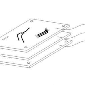
- High-frequency PCBs often adopt a multilayer structure to achieve complex circuit layout and signal transmission. The lamination process between layers needs to be strictly controlled to ensure a tight bond between each layer while avoiding introducing additional losses and non-uniformities.
Surface treatment:
- To improve solderability and signal transmission performance, high-frequency PCBs usually use special surface treatment methods, such as gold plating, electroless nickel gold, rather than the common tin spraying treatment.
Electromagnetic compatibility (EMC) and electromagnetic interference (EMI) considerations:
- During the design and manufacturing process of high-frequency PCB , full consideration is given to electromagnetic compatibility and electromagnetic interference issues. Through reasonable layout, shielding, filtering, and other measures, it is ensured that high-frequency PCBs do not interfere with surrounding electronic devices during operation and are themselves capable of resisting external electromagnetic interference.
In conclusion, high-frequency PCBs, with their special materials, fine design, and high-precision manufacturing processes, can effectively handle high-frequency electronic signals and provide crucial support for the development of modern electronic technology.
The common types and characteristics of board materials for high-frequency PCBs
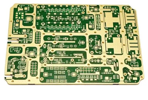
The common types of board materials used for high-frequency PCBs and their characteristics are as follows:
1. Rogers PCB boards:
- They have a low loss factor, which can effectively reduce energy loss during signal transmission.
- The dielectric constant is stable, which is conducive to precise impedance control.
- The operating frequency range is wide and is suitable for high-frequency and microwave frequency bands.
2. Taconic PCB boards:
- Provide different dielectric constant options to meet specific design requirements.
- Have good thermal stability and are suitable for high-temperature working environments.
- Exhibit excellent moisture resistance.
3. Polytetrafluoroethylene (PTFE) PCB boards:
- Have extremely low loss characteristics and are suitable for high-demanding high-frequency applications.
- The dielectric constant is uniform, contributing to good signal transmission.
- Have high chemical stability.
4. Ceramic-filled PTFE PCB boards:
- Combine the high strength of ceramics with the low loss advantages of PTFE.
- Improve the mechanical properties of PTFE boards.
5. Polyphenylene ether (PPE) boards:
- Have a relatively low cost while performing well within a certain frequency range.
- Have good moisture resistance and dimensional stability.
These boards have their own advantages in high-frequency applications. When choosing, comprehensive consideration should be given based on specific frequency requirements, performance indicators, cost budgets and other factors.
The dielectric constant range of high-frequency PCB boards
The following are the approximate data of the dielectric constant range of some common high-frequency PCB board materials:
Board type Dielectric constant
| Material for HF PCBs | Dk | Df | Tg | Td | Z CTE | Surface Resistivity | Thermal Conductivity | Peel |
| (@10GHz) | (@10GHz) | (°C) | (°C) | (ppm/°C) | (MΩ) | (W/m·K) | Strength | |
| (N/mm) | ||||||||
| Rogers RO4003C | 3.38 | 0.0027 | >280 | 425 | 46 | 4.2 x 10⁹ | 0.71 | 1.05 |
| (Reinforced Hydrocarbon/Ceramic) | ||||||||
| Rogers RO4350B | 3.48 | 0.0037 | >280 | 390 | 32 | 5.7 x 10⁹ | 0.69 | 0.88 |
| (Reinforced Hydrocarbon/Ceramic) | ||||||||
| RT/duriod 5870 | 2.33 | 0.0012 | – | 500 | 173 | 2 x 10⁷ | 0.22 | 27.2 |
| (Reinforced PTFE) | ||||||||
| RT/duroid 5880 | 2.2 | 0.0009 | – | 500 | 237 | 3 x 10⁷ | 0.2 | 31.2 |
| (Reinforced PTFE) | ||||||||
| Rogers RO3003 | 3 | 0.0013 | – | 500 | 25 | 1 x 10⁷ | 0.5 | 2.2 |
| (Ceramic-filled PTFE) | ||||||||
| Rogers RO3006 | 6.2 | 0.002 | – | 500 | 24 | 1 x 10⁵ | 0.79 | 1.2 |
| (Ceramic-filled PTFE) | ||||||||
| Rogers RO3010 | 10 | 0.0022 | – | 500 | 16 | 1 x 10⁵ | 0.95 | 1.6 |
| (Ceramic-filled PTFE) | ||||||||
| isola IS620 | 4.5* | 0.008 | 220 | – | 55 | 2.8 x 10⁶ | – | 1.2 |
| (E-fibre glass) | ||||||||
| AGC Taconic RF-35 | 3.5** | 0.0018 | 315 | – | 64 | 1.5 x 10⁸ | 0.24 | 1.8 |
| (Ceramic) | ||||||||
| AGC Taconic TLX | 2.5 | 0.0019 | – | – | 135 | 1 x 10⁷ | 0.19 | 2.1 |
| (PTFE) | ||||||||
| AGC Taconic TLC | 3.2 | – | – | – | 70 | 1 x 10⁷ | 0.24 | 2.1 |
| (PTFE) | ||||||||
| ARLON 85N | 4.2* | 0.01 | 250 | 387 | 55 | 1.6 x 10⁹ | 0.2 | 1.2 |
| (Polyimide) |
It should be noted that the dielectric constant is not a fixed value and may vary with factors such as frequency and temperature. In practical applications, the detailed technical specifications provided by the manufacturer should be referred to in order to obtain accurate and up-to-date dielectric constant values for specific board materials under specific conditions. Also, the dielectric constant of similar board materials produced by different manufacturers may also vary to some extent.
In addition, the relative dielectric constant of FR4 material (common glass fiber epoxy board) is usually between 4.2 - 4.7, but its dielectric constant may also change with temperature and frequency. In high-frequency applications, the performance of FR4 boards may not be as good as that of the above-mentioned specialized high-frequency PCB boards.
There are many significant differences between the production of high-frequency PCB and ordinary FR4 PCB:
Firstly, there is a difference in the board material. High-frequency PCB tends to select special materials with low loss factor and stable dielectric constant. Materials like Rogers and Taconic can effectively guarantee the transmission quality of high-frequency signals; ordinary FR4 PCB mostly uses the relatively low-cost FR4 material, whose performance under high frequencies is not as good as that of specialized high-frequency materials.
In terms of manufacturing accuracy, high-frequency PCB has extremely strict requirements. The width and spacing of the lines need more precise control, and the alignment accuracy between layers must reach a higher standard to minimize distortion and loss during high-frequency signal transmission; while ordinary FR4 PCB has relatively looser requirements for these accuracies.
In the process flow, high-frequency PCB often includes more special treatment steps. For example, when drilling holes, more precise control of the hole diameter and hole wall roughness is required to reduce the impact on high-frequency signals; in the surface treatment link, special coating processes may be used to optimize signal transmission. The process flow of ordinary FR4 PCB is relatively conventional and simplified.
For impedance control, high-frequency PCB has extremely strict requirements. Because high-frequency signals are very sensitive to impedance changes, during the design and production process, it is necessary to accurately calculate and adjust the parameters of each layer to ensure impedance consistency; the impedance control of FR4 PCB usually only needs to meet general standards.
The difference in the testing link is also very obvious. High-frequency PCB requires a series of complex high-frequency performance tests, such as the measurement of indicators like insertion loss, return loss, and crosstalk; ordinary FR4 PCB mainly tests basic electrical properties, such as conductivity and resistance.
In which applications are high-frequency PCBs used in modern electronic products?
High-frequency PCBs have extensive applications in modern electronic products. Common application fields include:
1. Communication equipment: Such as antennas and transceiver modules of 5G base stations, used to ensure the stability and high-speed transmission of signals;
2. Radio frequency equipment: Antennas, filters, power amplifiers, etc. within it require high-frequency PCBs to ensure the quality and stability of signal transmission;
3. RF equipment: Such as radars, satellite communications and other devices operating in high-frequency bands. High-frequency PCBs can achieve functions such as rapid signal forwarding, convenient switching and high-speed acquisition, and ensure the accuracy and stability of signal transmission;
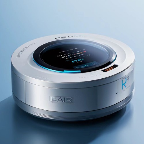
4. Internet of Things devices: In scenarios of large-scale interconnection and information interaction of Internet of Things devices, various sensors typically require high-frequency PCBs to complete signal acquisition and forwarding. For example, temperature and humidity sensors and light sensors in smart homes, as well as Internet of Things devices in fields such as smart logistics and smart healthcare, are used to achieve communication and data transmission between devices;
5. Automotive collision avoidance systems: High-frequency PCBs contribute to achieving rapid and accurate signal transmission and processing;
6. Satellite communication systems: Including devices such as satellite transceivers, which have high requirements for the stability and accuracy of signal transmission;
7. Wireless network equipment: High-frequency PCBs ensure efficient transmission of wireless signals;
8. Mobile communication products: Such as baseband chips and antennas of mobile phones;
9. Power amplifiers, low-noise amplifiers, etc.: Enhance the performance of signal amplification and transmission;
10. Passive devices such as power dividers, couplers, duplexers, and filters: Realize functions such as signal distribution, coupling, and filtering.
With the development trend of high-frequency electronics in devices, the importance of high-frequency PCBs is increasingly prominent. It has characteristics such as high transmission speed, stable signal transmission and strong anti-interference ability, and can meet the requirements of modern electronic products in high-frequency and high-speed signal transmission and processing.
In radar systems, high-frequency PCBs have several key applications, mainly including the following aspects:
In the transmitting part of the radar, high-frequency PCBs are used to carry and transmit high-power radio frequency signals. Their low-loss characteristics help ensure the strength and quality of the transmitted signal, reducing energy attenuation during transmission.
In the receiving part, high-frequency PCBs can precisely handle weak echo signals. Their good signal integrity and low noise performance help improve the sensitivity and resolution of the radar, thereby detecting targets more accurately.
In the signal processing unit, high-frequency PCBs can achieve high-speed and high-precision digital signal processing, rapidly analyzing and calculating the received radar signals.
In addition, high-frequency PCBs are also used in components such as frequency synthesizers and filters in the radar system to generate and filter the required operating frequencies, improving the performance and anti-interference ability of the radar.
In conclusion, with their excellent high-frequency performance, high-frequency PCBs play an important role in each key part of the radar, ensuring the efficient operation and precise detection ability of the radar system.
