Description
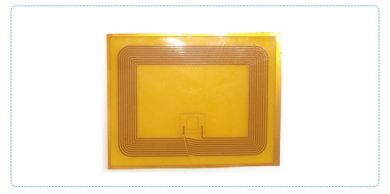
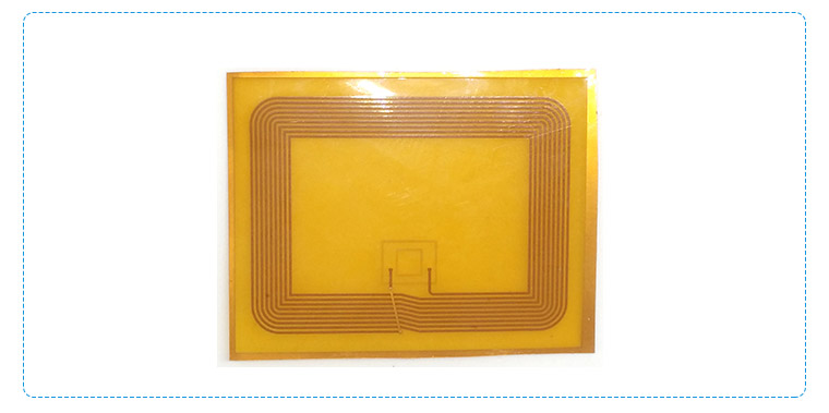
Layer:0.13mm
plate:Polyimide/PI
copper thick:1oz
surface finish:ENIG
min trace width/space:0.1mm/0.1mm
What are the wiring methods of the antenna FPC? There are mainly the following types:
1. Single-sided wiring of antenna FPC : This wiring method arranges the circuits on one side of the FPC, which is usually used for simple circuit connections.
2. Double-sided wiring of antenna FPC: The circuits are distributed on both sides of the FPC, which can realize a more complex circuit layout and improve the density and reliability of the wiring.
3. Antenna FPC Multi-layer wiring: By adding multiple conductive layers inside the FPC, more circuit connections and higher integration can be achieved.
4. Rigid-flex wiring of antenna FPC: It combines the characteristics of rigid circuit boards and flexible circuit boards. In the parts that require rigid support, rigid materials are used, while in the parts that need to be bent, flexible materials are used to meet specific application requirements.
5. Antenna FPC high-density wiring: Using thinner circuits and smaller spacings to achieve higher density wiring, which is suitable for electronic devices with strict space requirements.
6. Special-shaped wiring of antenna FPC: According to specific application requirements, the FPC is designed into a specific shape, such as a circle, square, or irregular shape to adapt to the special installation environment.
When choosing a wiring method of antenna FPC, the following factors need to be considered:
1. Electrical performance requirements of antenna FPC: According to the requirements such as the speed, frequency, and power of signal transmission, choose an appropriate wiring method and material.
2. Space limitations: According to the size and shape of the device, choose a wiring method that can adapt to the space requirements.
3. Antenna FPC reliability requirements: Consider factors such as the durability, anti-interference ability, and maintainability of the wiring.
4. Cost factors of antenna FPC: Different wiring methods have different costs, and an economical solution needs to be selected under the premise of meeting the performance requirements.
In practical applications, usually an appropriate antenna FPC wiring method is selected according to the specific product design and requirements. At the same time, relevant design specifications and standards need to be followed to ensure the quality and reliability of the wiring. If you need more detailed information, it is recommended to refer to relevant technical materials or consult a professional PCB designer.
How does an RF antenna FPC work?
An RF (Radio Frequency) antenna FPC works based on the principle of electromagnetic induction and radiation.
When an alternating current (AC) with a radio frequency flows through the antenna FPC, it generates an electromagnetic field around it. This electromagnetic field then propagates through space as electromagnetic waves.
The antenna FPC is designed to efficiently radiate and receive these electromagnetic waves. The shape, size, and orientation of the antenna FPC determine the frequency, polarization, and radiation pattern of the emitted or received signal.
When receiving a radio signal, the electromagnetic waves induce a voltage in the antenna FPC, which is then processed by the connected receiver circuitry to extract the information carried by the signal.
In essence, the antenna FPC acts as a transducer, converting electrical signals into electromagnetic waves for transmission and vice versa for reception.

An antenna FPC (Flexible Printed Circuit) typically connects to an electronic device through several common methods. One common way is via soldering. The connection points on the FPC and the corresponding pads on the device's circuit board are precisely aligned, and then solder is applied to create a secure electrical connection.
Another method is through the use of connectors. Specialized connectors are designed to mate with the FPC's contacts, allowing for a removable or detachable connection, which can be useful for maintenance or replacement.
In some cases, conductive adhesives or pressure contacts might also be employed. Conductive adhesives provide an electrically conductive bond, while pressure contacts rely on mechanical pressure to maintain the connection.
The choice of connection method depends on factors such as the design requirements of the electronic device, the space available, the level of reliability needed, and the manufacturing process.


