Description
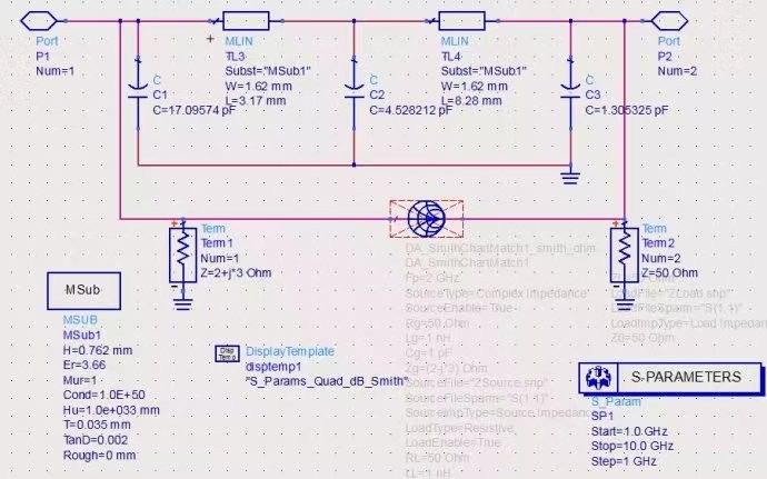
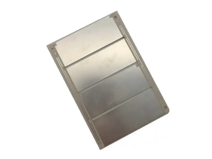
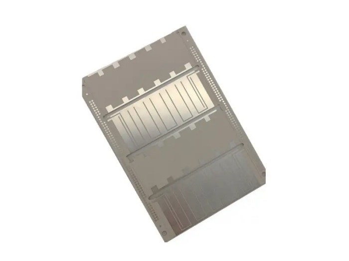
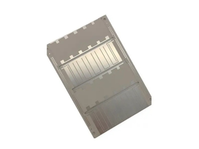
Rogers RO3003 High Frequency PCB
Number of floors: 2
Plate thickness:0.762mm
Plate used: rogers3003
Dielectric constant: 3.0 ± 0.05
Dielectric loss factor:0.0013
Minimum hole diameter: 0.2mm
Surface treatment:immersion silver
Minimum trace width/distance: 0.2mm/0.25mm
Process characteristics: high-frequency materials, Ro3003
Application: automotive radar, RF coupler, aerospace and national defense
Rogers 3003 PCB is a printed circuit board (PCB) fabricated with Rogers 3003 material. Rogers 3003 is a high-frequency circuit material with the following characteristics:
- Ceramic-filled PTFE composite: Rogers 3003 is a PTFE composite with ceramic fillers added, and the application of this material makes the dielectric constant of Rogers 3003 have extremely high temperature stability and frequency stability.
- Low loss: The dielectric loss of Rogers 3003 laminate at 10 GHz is 0.0013, which makes it very suitable for use in high-frequency circuits such as radio frequency and microwave circuits.
- Good dimensional stability: The thermal expansion coefficient of Rogers 3003 in the X and Y directions is 17 ppm/°C, which is comparable to that of copper, so that the typical value of the material due to etching shrinkage (baking after etching) can be lower than 0.5 mil/inch, showing excellent dimensional stability.
If you need to manufacture Rogers 3003 PCB, it is recommended to cooperate with us who have relevant experience and techniques to meet your needs and ensure product quality.
The Rogers RO3003 High Frequency PCB is suitable for applications in the frequency range of DC to 10 GHz.

The working principle of a Rogers RO3003 High Frequency PCB is based on its ability to handle and propagate high-frequency electrical signals with minimal losses and distortion.
Rogers RO3003 is a dielectric material with specific electrical properties that make it suitable for high-frequency applications. When an electrical signal is applied to the PCB traces, the material's low dielectric constant and low dissipation factor help to reduce signal attenuation and phase shift as the signal travels through the circuit.
The rogers RO3003 PCB layout and design, including the width and spacing of the traces, also play a crucial role. They are engineered to control impedance, minimize reflections, and ensure efficient signal transmission within the desired frequency range.
Overall, the combination of the material properties of Rogers RO3003 and the optimized PCB design enables the board to function effectively in high-frequency electronic systems, allowing for reliable and accurate signal processing and communication.
How can I measure the dielectric constant and dissipation factor of Rogers RO3003 High Frequency PCB?
To measure the dielectric constant and dissipation factor of Rogers RO3003 High Frequency PCB, you can use the following methods:
1. Resonant cavity method: This involves placing the PCB Rogers RO3003 sample in a resonant cavity and measuring the resonant frequency and quality factor of the cavity. From these measurements, the dielectric constant and dissipation factor can be calculated.
2. Transmission line method: You can fabricate a transmission line structure on the PCB and measure the propagation characteristics of the signal along the line. This data of Rogers RO3003 can then be used to determine the dielectric properties.
3. Capacitance measurement of Rogers RO3003: By creating a capacitor structure using the PCB material and measuring its capacitance and loss, the dielectric constant and dissipation factor can be estimated.
Rogers RO3003 specialized test equipment such as vector network analyzers (VNAs) are commonly used for these measurements. It's important to follow standardized test procedures and ensure accurate sample preparation and calibration of the measurement equipment to obtain reliable results.


