Description
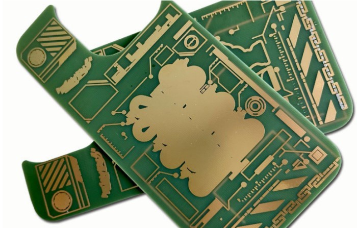
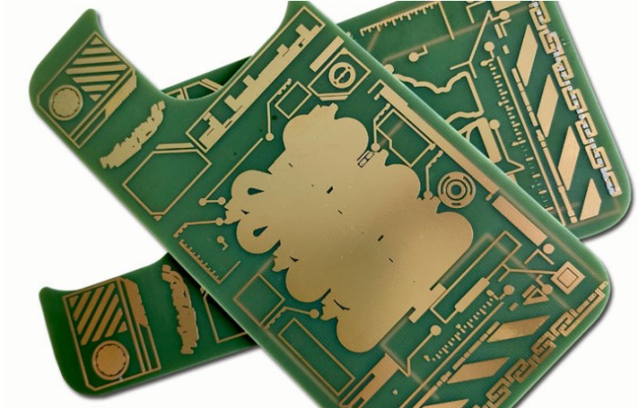
This is rigid PCB,
material is FR-4 with green soldermask,
surface treatment ENIG (immersion gold) ,
high TG 170, IPC class III,
1oz copper thick,
1.6mm board thick
min hole 0.3mm
min trace width/min distance 12mil
Product application: automobile power board
Heavy/thick copper PCB is a kind of printed circuit board (PCB) with special structure and performance. The thickness of the copper foil is generally 1 ounce or more. Through special processes, the thickness of the copper foil is increased to levels such as 2 ounces, 3 ounces, 4 ounces and 5 ounces, or even higher. Compared with the PCB with the standard copper foil thickness of 1 ounce or 2 ounces, the copper layer thickness of the heavy copper PCB far exceeds this standard and can reach 4 ounces, 6 ounces or even more.
Heavy/thick copper PCB has the following characteristics and advantages:
- High conductive performance: Due to the thicker copper layer, heavy/thick copper PCB has lower resistance and better conductive performance, which can meet the needs of high-current and high-power applications.
- High carrying capacity: Heavy/thick copper PCB can withstand higher mechanical stress and thermal stress, and has better reliability and stability.
- Excellent heat dissipation performance: The thick copper layer of heavy/thick copper PCB can conduct heat effectively and improve the heat dissipation efficiency of the circuit board, which is suitable for high-power electronic devices and applications with high heat dissipation requirements.
- High precision and high density: Heavy/thick copper PCB can achieve higher circuit density and smaller line width/line pitch, meeting the requirements of miniaturization and high performance of modern electronic devices.
Heavy/thick copper PCB is widely used in fields such as new energy vehicles, charging piles, aerospace, rail transit, medical equipment, industrial control, etc., and is an indispensable key component in these fields.
The classification of thick copper PCB boards?
1. Classified by copper thickness: such as 3 oz, 4 oz, 5 oz or even thicker copper layer thickness.
When the copper thicknesses of 3oz, 4oz, and 5oz PCB boards are different, the main differences include the following aspects:
- - Current-carrying capacity: The greater the copper thickness, the greater the current that the board can carry. The 5oz copper thickness PCB board usually has a stronger current-carrying capacity than the 3oz and 4oz ones and is suitable for applications with high power and large current.
- - Heat dissipation performance: A thicker copper layer helps to dissipate heat better. Therefore, the heat dissipation effect of the 5oz copper thickness PCB board is usually better than that of the 3oz and 4oz boards, which is very important in electronic devices with large heat generation.
- - Cost: An increase in copper thickness will lead to an increase in the cost of PCB manufacturing. Generally speaking, the 5oz copper thickness PCB board is more expensive than the 3oz and 4oz ones.
- - Processing difficulty: A thicker copper layer may increase the processing difficulty during the PCB manufacturing process, such as in the processes of etching and drilling.
- - Signal transmission of thick copper PCB : In terms of high-frequency or high-speed signal transmission, a thicker copper layer may have a certain impact on signal integrity, requiring more elaborate design and optimization.
In conclusion, the choice of which copper thickness PCB board depends on the specific application requirements, cost budget, and performance requirements.
2. Heavy/thick copper PCB classified by application fields: such as power electronics, industrial control, communication equipment, automotive electronics, etc.
3. Heavy/thick copper PCB Classified by the number of layers: including single-layer thick copper PCB boards, double-layer thick copper PCB boards and multi-layer thick copper PCB boards.
4. Heavy/thick copper PCB Classified by manufacturing processes: such as thick copper PCB boards made by different processes such as electroplating thickening and direct lamination of thick copper foil.
5. Heavy/thick copper PCB Classified by materials: Thick copper PCB boards made of different substrate materials such as FR-4, aluminum substrate, ceramic substrate, etc.
When designing thick copper PCB boards, how should the line width and gap be controlled?
When designing thick copper PCB boards, the control of line width and gap needs to comprehensively consider multiple factors, including the finished copper thickness, manufacturing process capabilities, current carrying requirements, etc.
Generally speaking, the thicker the copper thickness of the PCB, the more severe the side etching phenomenon during etching, and the easier it is for the actual width of the lines to be affected. To avoid the lines becoming thinner after etching or problems such as open circuits and short circuits, during the design process, it is necessary to appropriately compensate the lines and increase the line width and line gap based on the size of the finished copper thickness of the PCB, combined with the process capabilities and etching factors of the factory.
The specific process capabilities of different factories may vary. The following are some common suggestions (for reference only):
Inner layer (It is recommended to design according to the process capabilities in the first column):
| Finished copper thickness | Minimum line width | Min line gap |
| 1oz | 3mil | 3mil |
| 2oz | 4mil | 4mil |
Outer layer (H represents the finished copper thickness):
| Finished copper thickness | Minimum line width | Min line gap |
| H<=1oz | 3.5mil | 3.5mil |
|
1OZ |
4mil | 4mil |
|
2OZ<H<=3oz |
5mil | 5mil |
In actual design, it is recommended to fully communicate with the PCB manufacturer to understand their specific manufacturing capabilities and recommended line width and line gap ranges to ensure that the design can meet the requirements of production and processing. At the same time, factors such as the power requirements of the circuit, signal frequency, and impedance control should also be considered to achieve the performance and reliability of the circuit board.
In addition, some methods can be used to improve the accuracy of line width and gap control. For example, indicator strips can be set on the edge of the circuit board, and the etching speed can be adjusted accordingly by observing the changes in the etching width of the line segments on the indicator strips to ensure the consistency of the etched line width in batch production.
It should be noted that the above data are only general guidelines, and adjustments and optimizations should be made based on the specific situation during actual thick copper PCB boards design.
When designing thick copper PCB boards, how can the design of copper thickness and line width be optimized to reduce the wiring congestion of a single layer?
To optimize the design of copper thickness and line width of thick copper PCB boards to reduce the wiring congestion of a single layer, the following methods can be considered:
1. Accurately assess the current requirements of thick copper PCB boards: Understand the current that each line and component needs to carry in the circuit, which serves as the basis for determining the appropriate copper thickness and line width.
2. Select the line width based on the copper thickness of PCB: Generally speaking, a larger copper thickness can be paired with a wider line width. For example, for an inner layer with 1 ounce (oz) copper thickness, the etching compensation might be 1 mil, while for 2 ounces copper thickness, the etching compensation might be 2 mil. This can maintain uniform current distribution and reduce line impedance and heat concentration issues.
3. Utilize multi-layer board design of thick copper PCB boards: In areas with high wiring density, use multi-layer boards to distribute some current paths to different layers, thereby reducing the wiring pressure of a single layer.
4. Thick copper PCB boardsConduct simulation analysis: Use simulation software to simulate current distribution and thermal effects, and predict potential problem areas in advance to optimize the wiring and copper thickness design.
5. Local thickening or widening: On critical high-current lines, methods such as window opening or thickening the copper plating can be used to increase the local current-carrying capacity while minimizing the impact on the overall wiring density.
6. Communicate with the thick copper PCB boardsmanufacturer: Understand the capabilities of the PCB manufacturing factory and the recommended range of line width and copper thickness to ensure that the design is within the manufacturability range.
In addition, the heat dissipation design of the circuit board also needs to be comprehensively considered. Good heat dissipation helps improve the current-carrying capacity and alleviate the contradiction between wiring density and current-carrying capacity of thick copper PCB boards. At the same time, note that the thicker the finished copper thickness, the more severe the side etching of the line, and the line may become thinner after etching. Therefore, when calculating the impedance, the actual upper and lower line widths need to be considered. In actual design, these parameters should be continuously adjusted and optimized according to the specific circuit design requirements and actual application scenarios to achieve the best balance.
Here are some layout techniques for thick/heavy copper PCB boards:
1. Thick copper PCB board Layered wiring: Distribute the lines with different functions and current requirements on different PCB layers to reduce the wiring density on the same layer and reduce mutual interference.
2. Plan power and ground lines of thick copper PCB board: Allocate wider traces for power and ground lines, taking advantage of the thick copper to reduce resistance and increase current carrying capacity. Ensure that the traces of power and ground lines are short and direct to reduce noise and voltage drop.
3. Increase trace spacing of thick copper PCB board: Appropriately increase the spacing between traces, which helps to reduce crosstalk and improve signal integrity. For high-power and high-frequency lines, the spacing should be larger.
4. Corner handling of thick copper PCB board : Use arcs or 45-degree angles at the corners of traces instead of right angles, which can reduce signal reflection and current concentration.
5. Thick copper PCB board grouped wiring: Group related signal lines and maintain the consistency of the traces within the group and the uniformity of the spacing to improve the anti-interference ability.
6. Heat dissipation consideration of thick copper PCB board: For components and lines that generate more heat, wire near heat dissipation holes or heat dissipation areas, or add heat dissipation pads on the traces to enhance the heat dissipation effect.
7. Via design of thick copper PCB board: Reasonably use vias to connect lines on different layers, and select the appropriate via size and quantity to ensure good current passing capacity and signal transmission.
8. Avoid right-angle traces: Right-angle traces may cause signal reflection and radiation at high frequencies. Try to use curved or obtuse-angle traces.
9. Follow wiring rules: Wire according to the wiring rules and constraints in the PCB design software to ensure compliance with manufacturing processes and electrical performance requirements.
10. Reserve test points of thick copper PCB board: Reserve test points at key positions for convenient later debugging and fault diagnosis.
These techniques can help you improve the wiring quality and performance of thick copper PCB boards and ensure the stability and reliable operation of the circuit.
What should be noted when manufacturing thick copper PCBs?
The following points should be noted when manufacturing thick copper PCBs:
1. Material selection: Choose high-quality substrate materials that can withstand the thick copper process and have good electrical and thermal properties.
2. Equipment capacity: Ensure that the production equipment is capable of handling the processing of thick copper layers, including processes such as electroplating and etching.
3. Electroplating uniformity: During the electroplating of thick copper PCB, ensure the uniformity of the coating to avoid local areas that are too thick or too thin.
4. Etching accuracy: Due to the difficulty of etching thick copper PCB, it is necessary to precisely control the etching parameters to obtain accurate circuit patterns.
5. Lamination quality: Ensure that the layers are tightly laminated without bubbles, delamination, and other defects, especially at the junction of the thick copper layer and other layers.
6. Drilling accuracy: Thick copper PCB has higher requirements for drilling. Ensure the positional accuracy of the drilling and the accuracy of the hole diameter size.
7. Thermal management: Consider the heat generated by thick copper and take appropriate heat dissipation measures during the production process to prevent the board from deforming or affecting performance.
8. Quality inspection: Strengthen the inspection of thick copper PCBs, including appearance inspection, electrical performance testing, thickness measurement, etc., to ensure that the products meet quality standards.
9. Process parameter control: Strictly control various process parameters during the production process, such as temperature, pressure, time, etc.
10. Operator skills: Train the operators to be familiar with the production process and operation key points of thick copper PCBs to reduce human errors.
In conclusion, manufacturing thick copper PCBs requires strict control of each link to ensure the quality and performance of the products.
The applications of thick copper PCB in charging piles?
Thick copper PCB has the following applications in charging piles:
1. Power module: The power conversion part in the charging pile needs to handle high current and high power. Thick copper PCB can provide excellent current carrying capacity to ensure efficient and stable power transmission.
2. Charging control circuit: Responsible for controlling parameters such as current, voltage and charging time during the charging process. Thick copper PCB helps to ensure the stability and reliability of the circuit, reducing heat generation and signal interference.
3. Power management system: Optimize the distribution and management of power. Thick copper PCB can withstand large current fluctuations and improve power efficiency.
4. Driving circuit: Drive various power devices in the charging pile. Thick copper PCB can effectively reduce line resistance and improve driving performance and stability.

In conclusion, due to its good heat dissipation performance and high current carrying capacity, thick copper PCB plays an important role in charging piles, which have high requirements for power and stability.


