Analysis of the cause of the black powder found between the PCB and the component
Analysis of the cause of the black powder found between PCB and the component
Wu Gong: Please teach you teachers, the current product has such a problem: the product reported fault, inspection found that the connector adjacent pins measured resistance value of only a dozen k, with a hot air gun blowing soldering point between the pins to restore the insulation, the middle of the x-ray inspection to confirm that there is no tin beads and other metal excess, I would like to ask you teachers have not encountered the same problem, or what may be the reason for this, thank you!
WuMin: There may be tiny metal filaments or ECM micro-current channels between the two pins on the side of the board, which can't be detected by X-ray.
WM: Sir, can this problem be solved by hot air blowing? Currently, there are two products with this problem, one is fine after blowing the faulty solder joints with hot air, and the other has no change, and the resistance value is about 4 times this level.
Zhai Daqing: The product is not clean, the ionic pollutant index exceeds the standard, which leads to the decrease of insulation resistance when the product is damp.
Wu Min: After heating, the solder will melt and disconnect, remove the electrical connector, carefully check the cleaning and drying
Wu: Understand, let's follow this line of thought and then check the other one.
WU Min: If the resistance value meets the requirements, then solder the connector.
Wu: I understand, thank you for the picture
Liao Xiaobo: It is possible that when soldering the connector pins, the flux climbed up to the inside of the plastic shell and was not effectively cleaned. Product service process, these flux residues absorb moisture, the solder pin plating constitutes a corrosion, resulting in the appearance of white, fluffy oxide. This oxide reduces the insulation resistance between the connector wires.
Even if the flux residue does not corrode the solder pin plating, as long as the flux residue is whitish to the point of being visually visible after absorbing moisture, it is entirely possible that it will affect the insulation resistance of the close-pitch connector.
Wu Min @ Liao Xiaobo: Ionic residues in the flux, hydrolysed to form ionic channels, will lead to a drop in insulation resistance, the other oxides will not conduct electricity. This must be a very large number of flux use, and cleaning is very unclean there are a large number of residues, otherwise it is difficult to appear this type of defect.
Wu: We are using selective soldering and water cleaning process to do the soldering and cleaning, the process parameters than the previous batch did not change, and now observe also did not find the white oxide, so now it is more confusing.
And this fault product production time is not long, belongs to the product, check the production parameters spray flux amount did not suddenly increase, so now can not touch the reason!
Liao Xiaobo:@Wu Gong: Review whether all the neighbouring leads between the weak insulation problems?
WU and: other do not have this problem, now suspect that the introduction of excess, but and hot air blowing after the disappearance of the fault is a bit of a contradiction!
Yinguoliang@Wuhe: What is the PITCH of the connector? How much is the PITCH of the connector? How many products have been mass-produced to appear in two cases? In addition, PCB using what process processing? How many layers? Single-sided or double-sided?
Wu: 8 layers, immersion nickel gold, double-sided, through-hole, 2 out of 5 units have this problem.
Yin Guoliang: How much is the PITCH of the connector?

Wu Gong: 1.9
Liao Xiaobo: It is recommended to check whether the components connected to these two pins in the circuit have poor insulation problems.
Wu Xiaoyi: OK, thank you!
Wu Min @LiaoXiaoBo: After heating with a hot air gun, the problem of a product is solved. There is a high probability that the defect is still related to the assembly process of the device. Of course, you can also check the periphery to rule out accidental factors.
Liao Xiaobo: Mr. Wu, after reading the questioner’s statement, my first feeling was the same as yours. But since we have had that experience in troubleshooting, we put it forward for the questioner's reference.
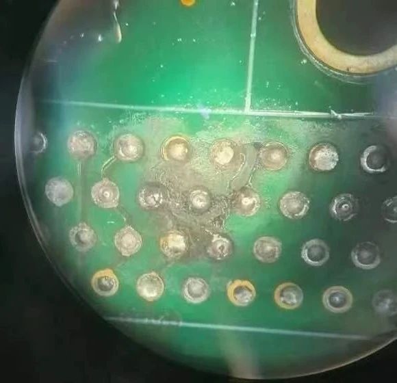
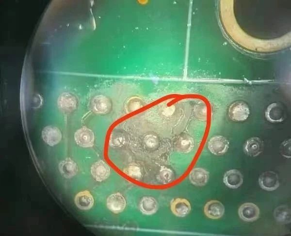
Wu Gong: Dear teachers, we disassembled yesterday’s faulty product and found some black powder between the board and the components. There is also black excess residue similar to glue residue left on the board. It can be washed away after cleaning, and then the insulation is also It's normal. This is the first time I've seen this black powder. I would like to ask the teacher what this might be?
Wu Min: Because it has not been exposed to high temperatures (greater than 300°C), the carbonized products of the flux residue can be eliminated, so I judged that the nozzle sprayed small tin slag into the middle of the printed board and the connector, and continuously sprayed tin and With the help of flux, the solder in the slag short-circuits the two pins, while the slag remains. During disassembly, it is spread flat on the surface of the printed circuit board due to external force. Tin slag can definitely be completely cleaned by the cleaning solution.
The tin slag inside the selective welding equipment must be checked and cleaned regularly, and equipment maintenance must not be neglected. The pin spacing is 1.9, and the minimum size on the outside of the two pads is estimated to be less than 1. It may also be that the spewing solder bridges the connection with the assistance of tin slag.
@Wu Gong: Mr. Wu, will the adhesion of this tin slag be very strong? When we were cleaning, we found that there were some areas that could only be removed with toothpicks. Can this kind of tin slag be seen by X-ray? We found no excess metal during X-ray inspection.
We tested that the short-circuit resistance between the two pins is about 17k. If the short-circuit is caused by tin slag, the resistance seems to be a bit high.
Wu Min: Flux is sticky, especially after curing. Unless there are large pieces of lead in the tin slag, the shadows under X-ray are indistinguishable.
Tin powder is an oxide and does not conduct electricity. It is estimated that there are solder filaments, which are very small, and there may also be some thin solder + flux ion residue. In short, there must be a leakage channel. Even if you take a slice, you may not be able to see it, let alone X-ray.
Wu Gong: I understand. Let’s check again along this line of thinking. I’m sorry to trouble you. Thank you!
Wu Min: You’re welcome! Although the other piece is back to normal, it is recommended to take it apart and clean it. Equipment must be well maintained.
Wu Gong: Yeah, I have already taken it apart, so I found that it is a common problem.
Wu Min: Defects caused by poor equipment condition.
Wu Gong: Let’s try to reproduce it
Shijianxing@wu gong: Are these pins powered? What is the voltage?

Wu Gong: 5v
Liao Xiaobo: Tin oxide is a black semiconductor
Wu Min: Oxidation of dynamic molten solder
1. Double wave peaks are widely used in the wave soldering process. The first wave peak is a wave wave with a relatively narrow wave width and a relatively fast flow rate of molten solder. The second wave peak is a laminar wave with a flat and stable wave surface, like a mirror, and the flow rate is relatively high. slower. New molten solder is constantly in contact with oxygen on the surface of the wave. Oxidized slag is formed when the molten solder flows rapidly. It is very different from static oxidation. There are three forms of solder slag formed during dynamic operation:
a. Surface oxide film: The molten solder in the tin furnace is oxidized at high temperature through contact with oxygen through its exposed surface in the air. This oxide film is mainly formed on the surface of the relatively static molten solder in the tin furnace and is film-like. The main component is SnO2. As long as the surface of the molten solder is not damaged, it can isolate the air and protect the inner layer of molten solder from further oxidation. This surface oxide film usually accounts for about 10% of the oxide slag.
b. Black powder. The particles of this kind of powder are very large. They are produced at the interface between the liquid level of molten solder and the mechanical pump shaft. They are distributed and accumulated in a circular shape around the shaft. The high-speed rotation of the shaft will cause friction with the molten solder, but because the molten solder has good thermal conductivity, the temperature of the molten solder around the shaft is not higher than the temperature in other areas. The formation of black powder is not due to the increase in friction temperature, but to the vortex of the surrounding molten solder surface caused by the rotation of the shaft, and the oxide is spheroidized by friction with the movement of the shaft. At the same time, friction can cause the surface energy of solder particles to increase and aggravate oxidation; it accounts for about 20% of the amount of oxide slag.
c. Oxidized slag. In the mechanical pump wave generator, there is violent mechanical stirring, which forms a violent vortex motion in the molten solder tank. In addition, the unreasonable design causes violent tumbling of the molten solder surface. These vortex and tumbling motions form an oxygen absorption phenomenon, and oxygen in the air is continuously sucked into the molten solder. Due to the limited inhaled oxygen, the oxidation process inside the molten solder cannot proceed as fully as the liquid level, so a large amount of silver-white sand-like (or tofu-like) oxidized slag is produced inside the molten solder. This kind of slag is formed in large quantities. The oxidation occurs inside the molten solder, and then floats to the liquid surface and accumulates in large quantities. It even occupies most of the space of the solder tank, blocks the pump chamber and flow channel, and finally causes the wave peak height to continuously decrease, and even damages the pump. blade and pump shaft; the other is that when the molten solder raised by the wave peaks flows back into the solder tank, the contact surface between the molten solder and the oxygen in the air is increased, and at the same time, a violent vortex movement is formed in the molten solder tank to form an oxygen absorption phenomenon. , thus forming a large amount of oxidized slag. These two types of slag usually account for 70% of the entire oxidized slag, causing the greatest waste. After applying lead-free solder, more oxide slag will be produced, and there will be more SnCu than SnAgCu. The typical structure is 90% metal plus 10% oxide.
2. Japanese scholar Tadashi Takemoto〈3〉 and others conducted tests on SnAg3.5, SnAg3.0Cu0.5, and Sn63Pb37 solders and found that the weight of oxidized slag of all solders increased linearly. The growth rate of oxidized slag of the three solders was almost The same, that is, its growth rate has little to do with the solder composition. The formation of oxidized slag is related to the fluid flow of molten solder. The instability and waterfall effect of the fluid may cause oxygen absorption and tumbling of molten solder, making the formation process of oxidized slag more complicated. In addition, from a process perspective, factors that affect the generation of oxide slag include wave peak height, welding temperature, welding atmosphere, wave peak interference, alloy type or purity, type of flux used, the number of PCBAs passing through the wave peak, and the quality of the original solder, etc. .
3. Structure of tin oxide slag
Usually what we call tin slag is mainly composed of tin oxide SnO2 (i.e. tin ash), tin Sn wrapped in tin oxide, and a small amount of carbonized material. The proportion of tin Sn wrapped in tin oxide is at least 50 % or more, some even as high as 90% (the specific content depends on the situation of slag fishing).
Tin oxide (i.e. tin ash) in tin slag is usually SnO2, gray powder, tetragonal, hexagonal or orthorhombic crystal; density is 6.95 g/cubic centimeter; melting point 1630°C; structural formula: O:SnO; molecular weight: 150.69; in Sublimes at 1800~1900℃; insoluble in water, alcohol, dilute acid and alkali; slowly soluble in hot concentrated alkali solution and decomposes; eutectic with strong alkali can form stannate; soluble in concentrated sulfuric acid or concentrated hydrochloric acid; Tin content: 70% - more than 90%.
4. The main component of oxide slag is SnO2, the oxygen content is about 5at%, and 90% of oxide slag is composed of metal. The solder entrained in the slag can conduct electricity by itself and does not require molten solder.


