Description
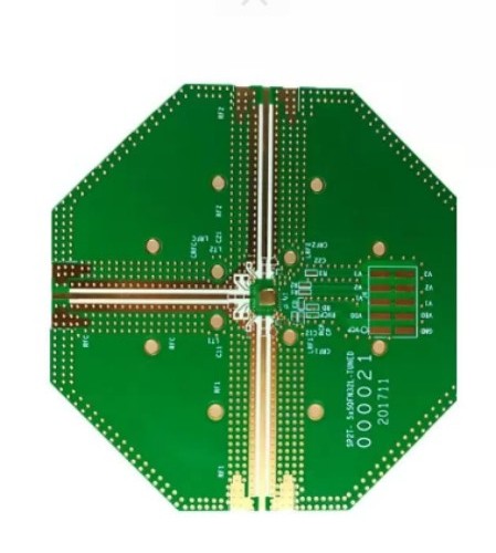
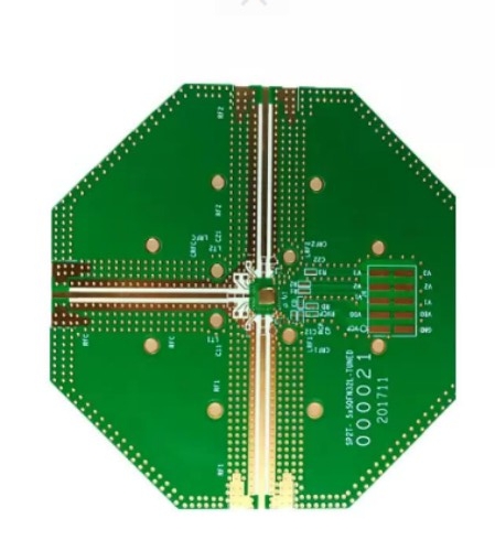
Rogers 4003C pcb
Number of floors: 2
Plate thickness: 0.8 ± 0.1mm
Plate used: rogers4003C
Dielectric constant(DC): 3.38 ± 0.05
Dielectric loss factor: 0.0027
Minimum hole diameter: 0.3mm
Surface treatment:immersion gold
Minimum trace width/distance: 0.3mm/0.2mm
Process characteristics: high-frequency materials, rogers4003C
1. Rogers4003C PCB is a kind of high-frequency circuit board, with the following characteristics:
- - Rogers4003C PCB high-frequency performance: The Rogers4003C material has good electrical performance at high frequencies and is suitable for applications in microwave and millimeter-wave frequencies.
- - Dielectric constant of Rogers4003C PCB: Its dielectric constant is 3.38 ± 0.05, which can meet the requirements of specific circuit designs.
- - Rogers4003C PCB loss factor: The loss factor is 0.0027 @ 10GHz, which helps reduce losses in signal transmission.
- - Thermal expansion coefficient of Rogers4003C PCB: The thermal expansion coefficient in the Z-axis is 46ppm/°C, and it has good thermal stability.
- - The Processing performance of Rogers4003C PCB: This material is compatible with standard epoxy resin/glass processing techniques and does not require special through-hole processing or operating procedures, which can reduce manufacturing costs.
Rogers4003C PCB is often used in fields with high requirements for high-frequency performance such as wireless communication, satellite communication, and radar systems. When using Rogers4003C PCB, attention should be paid to its design and manufacturing requirements to ensure the performance and reliability of the circuit board.
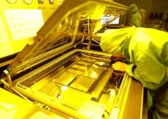
2. The manufacturing process flow of Rogers4003C PCB usually includes the following steps:
- -Material selection of Rogers4003C PCB: According to the application requirements, select the appropriate Rogers4003C material, including material type, thickness, and prepreg, etc.
- -Rogers4003C PCB Substrate preparation: Cut the core material into the required size and thickness, and perform chemical cleaning to prepare for further processing.
- -Drilling of Rogers4003C PCB: Drill holes in the Rogers core board.
- -Plated through holes: Perform plated through hole processing on the double-layer Rogers PCB.
- -Rogers4003C PCB lithography: Use a photomask to apply the pattern to the copper layer to define the traces and component positions on the circuit board.
- -Etching of Rogers4003C PCB: Remove the unnecessary copper areas through the etching process, and retain the defined traces and components.
-

- -Multilayer lamination: Laminate the inner layers and the prepreg in a sandwich structure under high temperature to form a multilayer board.
- -Rogers4003C PCB Solder mask and screen printing: The solder mask is used to protect the solder pads, while screen printing is used for marking and applying labels
- -Surface treatment of Rogers4003C PCB: The circuit board undergoes surface treatment to improve its corrosion resistance and solderability.
- -Testing and inspection of Rogers4003C PCB: Each finished circuit board is tested for electrical continuity, insulation resistance, and error-free operation, and visually inspected to ensure it meets quality standards.
To ensure the quality of Rogers4003C PCB, the following measures can be taken:
- 1. Validity of design documents of rogers4003C PCB: The project leader should check the PCB design documents and implement the corresponding approval procedures to ensure their validity.
- 2. Rogers4003C PCB Manufacturability: The project leader and technical personnel should strictly abide by the technical requirements to ensure the manufacturability of the PCB. The technical requirements should be accurately, clearly, reasonably explained, and in line with the current production process level and cost-effectiveness, while facilitating subsequent assembly, debugging and inspection.
- 3. Testability and standardization of rogers4003C PCB: Standardization personnel should conduct standardized inspections based on test points, structural styles, sizes, wiring, through holes and characteristics to ensure that the testability and manufacturability of the PCB meet the requirements of national and industrial standardization.
- 4. rogers4003C PCB Manufacturer's capabilities: The quality department and the purchasing department should investigate and approve the capabilities and manufacturing capabilities of the PCB manufacturer to ensure that they have sufficient manufacturing capabilities in the design project.
- 5. Inspection and confirmation before manufacturing rogers PCB: PCB designers must check and confirm the design drawings applied by the manufacturer many times before manufacturing to ensure that the manufactured PCB meets the requirements of the latest version.
- 6. Selection and testing of raw materials of rogers4003C PCB: Select substrate materials, conductive layers and covering layers that meet the requirements, and conduct strict testing to ensure that they meet relevant standards and specifications.
- 7. Control and optimization of the rogers4003C PCB manufacturing process: Strictly follow the prescribed process flow, and conduct necessary testing and verification to ensure the quality of each link.
- 8. Application of automated testing technology of rogers4003C PCB: Use advanced automated testing technologies such as optical testing systems and X-ray testing to detect potential defects and problems in a timely manner.
- 9. Comprehensive testing of the final product of rogers4003C PCB: After the PCB is manufactured, a comprehensive test is carried out, including electrical performance, welding quality, dimensional accuracy, etc., to ensure product quality.
The specific test methods for the high-frequency performance of Rogers 4003C PCB include the following:
- 1. Scattering parameter (S parameter) test of Rogers 4003C PCB: Use a vector network analyzer (VNA) to measure the reflection and transmission characteristics of the PCB at different frequencies. S parameters include S11 (reflection coefficient), S21 (transmission coefficient), etc., which can intuitively reflect the transmission and reflection of high-frequency signals.
- 2. Insertion loss test of Rogers 4003C PCB: By measuring the power loss of the signal when passing through the PCB transmission line, evaluate the signal attenuation degree of the PCB at high frequencies.
- 3. Return loss test of Rogers 4003C PCB: Determine the amount of energy reflected back by the signal on the PCB line to measure the matching degree and high-frequency performance of the PCB and the connected device.
- 4. Phase delay test of Rogers 4003C PCB: Measure the phase change of the high-frequency signal in the PCB transmission line to evaluate the consistency and accuracy of signal transmission.
- 5. Rogers 4003C PCB impedance measurement: Use an impedance analyzer or VNA-based impedance test function to measure the impedance value of the PCB line to verify whether it meets the design requirements and ensure a good high-frequency signal transmission match.
- 6. Rogers 4003C PCB eye diagram test: In high-speed digital signal transmission, by observing the opening degree and shape of the eye diagram, evaluate the high-frequency signal integrity and noise margin of the PCB.
- 7. Electromagnetic compatibility (EMC) test of Rogers 4003C PCB: Detect the electromagnetic radiation generated by the PCB during high-frequency operation and its sensitivity to external electromagnetic interference to ensure that it complies with relevant standards and regulations.
-

These test methods can help comprehensively evaluate the high-frequency performance of Rogers 4003C PCB to meet the requirements of specific applications.
The high-frequency performance of Rogers 4003C PCB is mainly manifested in the following aspects:
- 1. Low loss characteristics: In high-frequency signal transmission, it can significantly reduce the attenuation of the signal, ensuring that the signal strength remains at a high level during the transmission process, thereby reducing energy loss.
- 2. Rogers 4003C PCB has stable dielectric constant: The dielectric constant is relatively stable at high frequencies, which helps maintain the consistency and accuracy of signal transmission and reduces signal distortion.
- 3. Rogers 4003C PCB good impedance control: It can precisely control the impedance of the line, enabling a good match of high-frequency signals during transmission, reducing reflection and standing waves, and improving the efficiency and quality of signal transmission.
- 4. Low dispersion characteristics of Rogers 4003C PCB: The difference in the propagation speed of the signal at different frequencies is small, reducing frequency-related signal distortion and ensuring stable transmission within the wide frequency band.
- 5. Rogers 4003C PCB excellent thermal stability: In the case of heat generation during high-frequency operation, its performance is not significantly affected and it can still maintain stable high-frequency characteristics.
Rogers 4003C PCB has various applications in electronic products, including but not limited to the following aspects:
- 1. Rogers 4003C PCB apply in wireless communication devices: Such as 5G base stations, mobile phone signal amplifiers, wireless access points, etc. Its good high-frequency performance helps achieve efficient signal transmission and reception.
- 2. Rogers 4003C PCB apply in satellite communication systems: Used in satellite transceivers, satellite navigation equipment, etc., it can work stably at high frequencies and in harsh conditions in the space environment.
- 3. Rogers 4003C PCB apply in radar systems : In fields such as automotive radar and security radar, it can ensure accurate signal detection and rapid response.
- 4. Aerospace electronic equipment used by rogers 4003C PCB: Suitable for communication, navigation and monitoring systems on aircraft, meeting the requirements of light weight and reliable performance.
-

- 5. High-performance computers and servers used by rogers 4003C PCB : It helps improve the efficiency and stability of high-speed data transmission.
- 6. Rogers 4003C PCB apply in medical equipment: Such as medical imaging equipment, telemedicine terminals, etc., ensuring the precise operation of the equipment at high frequencies.
- 7. Automotive electronics used by rogers 4003C PCB: Such as advanced driver assistance systems (ADAS), in-vehicle communication systems, etc., ensuring reliable operation in a complex electromagnetic environment.


