PCB essential knowledge: what is FPC flex board and rigid-flex PCB board
I believe that people working in the electronics industry, for the circuit board or very familiar, whether you are engaged in software or hardware are inseparable from the circuit board, but most people may normally only contact the ordinary circuit board, have not seen or even heard of FPC flex board and rigid-flex board, the following to introduce you to what is FPC flex board and rigid-flex board, what is the difference between them and ordinary circuit boards, which need to pay attention to when designing PCBs. In the PCB design need to pay attention to where there are and so on.FPC rigid-flex board is also a class of circuit boards, but only in special circumstances will be used, in the introduction of rigid-flex board before, we first understand what is the circuit board?
Circuit boards can be divided by name: ceramic circuit boards, alumina ceramic circuit boards, aluminium nitride ceramic circuit boards, circuit boards, PCB boards, aluminium substrates, high frequency boards, thick copper boards, impedance boards, PCBs, ultra-thin circuit boards, ultra-thin circuit boards, printed (copper etching technology) circuit boards, etc., in any of the electronic equipment can be found, for the circuit of the electronic devices to play a fixed and connected role.
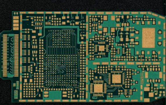
(High frequency boards)
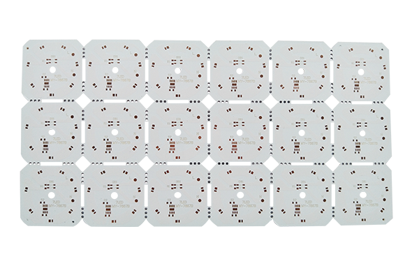
(High power LED aluminium substrate)
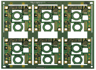
(Thick copper boards)
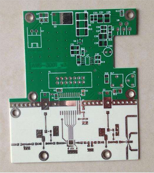
(Microwave RF communication board)
Next we first introduce what is FPC flexible board.
FPC circuit board is also known as flexible circuit board flexible circuit board is made of polyimide or polyester film as the substrate of a highly reliable, excellent flexible printed circuit board. FPC flexible boards can save the internal space of electronic products to a certain extent, making the assembly and processing of products more flexible. For example, the LCD/OLED and AMOLED display panels in smartphones are connected by FPC flexible boards, which are widely used in notebooks, digital cameras, as well as in medical, automotive and aerospace applications.
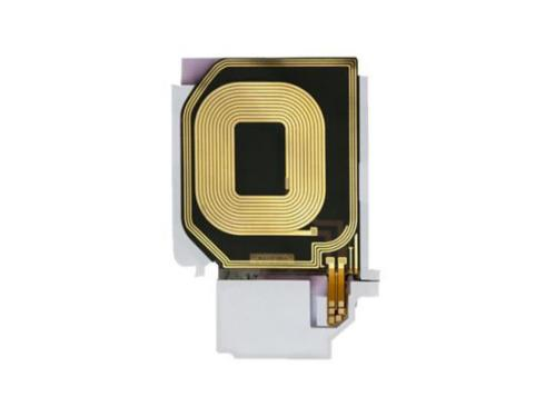
(Two-layer flexible coil board)
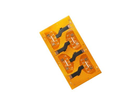
(Four-layer flexible impedance board)
As the name implies, the rigid-flex refers to the combination of flexible and rigid boards, after pressing together and other processes, according to the relevant process requirements, the formation of circuit boards with FPC characteristics and PCB characteristics.
The combination of rigid and flexible board has both FPC characteristics and PCB characteristics, so it can be used in some special requirements of the product, both a certain flexible area, but also a certain rigid area, to save the internal space of the product, reduce the volume of finished products, improve product performance is very helpful, but the combination of rigid and flexible board production is difficult and low yield rate, so its price is also more expensive, the production cycle is also relatively long. This is why they are more expensive and have a longer production cycle.
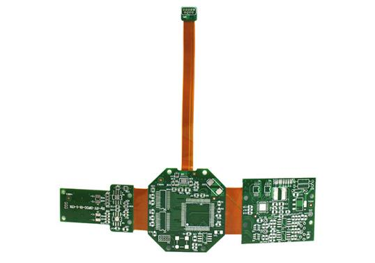
(rigid-flex digital image acquisition and processing board)
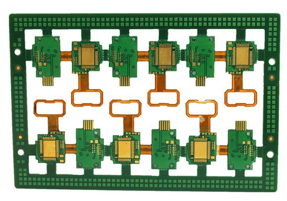
(4-layer FPC+FR4 rigid-flex PCB)
After we understand what is the FPC flex board and rigid-flex board, then in the actual design we need to pay attention to what?
The following should be noted in the layout.
1, the device needs to be placed in the hard area, the flexible area only for connection, which can improve the life of the board, to ensure the reliability of the board. If the device is placed in the flexible area, it will easily cause the pad to crack or, the character to fall off.
2, when the device is placed in the hard area, and the hard and soft area should be at least 1mm spacing.
When trace requires attention.
1, flex area graphics from the edge of the board at least 10mil, no holes, over-hole and rigid-flex of distance of at least 2mm.
2, the flex board area trace should be smooth, the corners need to be connected with rounded alignment, while straight lines and arcs should be vertical, pads need to add tear drop processing to avoid tearing
3, in the flex area edge need to use copper foil in the connection line bend reinforcement connection.
4, in order to achieve better flexibility, the bending area should avoid changes in the width of the alignment, as well as the uneven density of the alignment of the situation generated.
5、The surface and bottom layers of the trace should be staggered as far as possible to avoid overlapping of the surface and bottom layers.


